In this project I am interfacing the HC-SR04 ultrasonic sensor module to a Raspberry Pi to measure distance. Later on the Raspberry as well as the sensor will be part of an obstacle avoiding robot. I use my oscilloscope to check whether the sensor is working as announced.
A basic ultrasonic sensor consists of one or more ultrasonic transmitters (basically speakers), a receiver, and a control circuit. The transmitters emit a high frequency ultrasonic sound, which bounces off any nearby solid object. Some of that ultrasonic signal is reflected and detected by the receiver on the sensor. That return signal is then processed by the control circuit to calculate the time difference between the signal being transmitted and received. This time can subsequently be used to calculate the distance between the sensor and the reflecting object.
The HC-SR04 ultrasonic module operates at 5V with a current of some 15mA and measures the distance effectively starting from 2cm to 400cm. It has four pins: ground (GND), Echo Pulse Output (ECHO), Trigger Pulse Input (TRIG), and 5V Supply (Vcc). We power the module using Vcc, ground it using GND, and use our Raspberry Pi to send an input signal to TRIG.
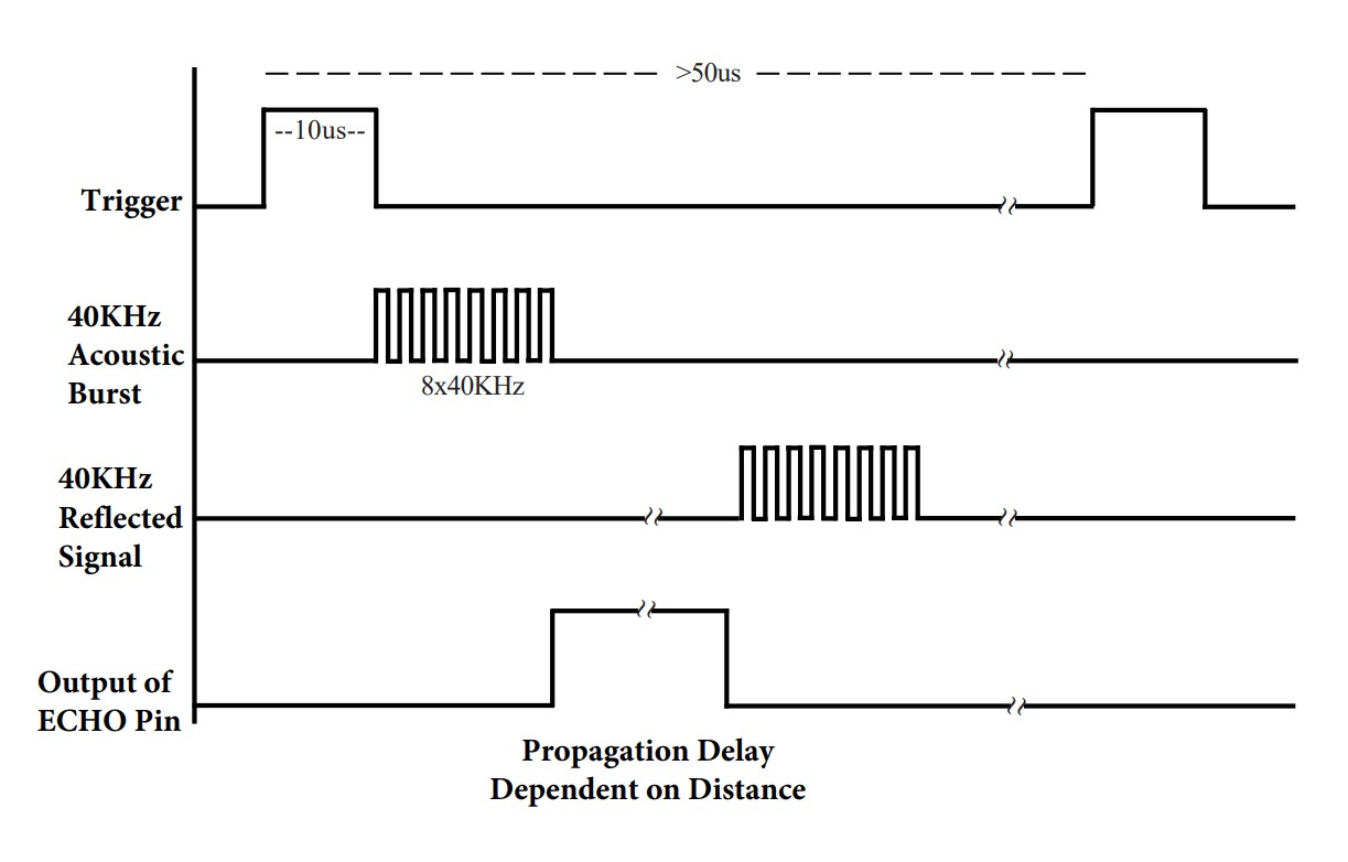
The HC-SR04 sensor requires a short 10-100us pulse to trigger the module, which will cause the sensor to start the ranging program (8 ultrasound bursts at 40kHz) in order to obtain an echo response. Once the 8 burst pattern is sent, the ECHO pin is set high (i.e 5V), and when the signal reflects and comes back the ECHO pin is set low (0V). This time duration for which the ECHO pin stays high is the time taken for the ultrasonic wave to travel and come back (round trip). The distance can then be calculated using the speed of sound 343m/s.
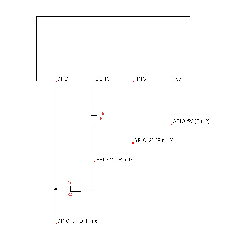
As mentioned above the operating voltage of the module is 5V. The input pin on the Raspberry Pi GPIO is only 3.3V tolerant. Sending a 5V signal into a 3.3V input port could damage the GPIO pins. We use a voltage divider to solve this problem. A voltage divider consists of two resistors (R1 = 1kOhm and R2 = 2kOhm) in series connected to an input voltage (V_in), which needs to be reduced to our output voltage (V_out). In our circuit, V_in will be ECHO, which needs to be decreased from 5V to our V_out of 3.3V.
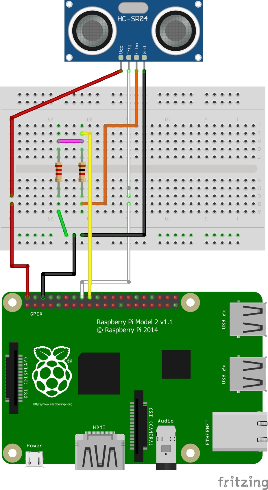
I am a big fan of the software fritzing which allows to draw neat schematics in next to no time. That’s how it will look like when all pins are connected using a breadboard and jumper wires:
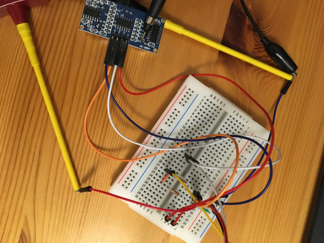
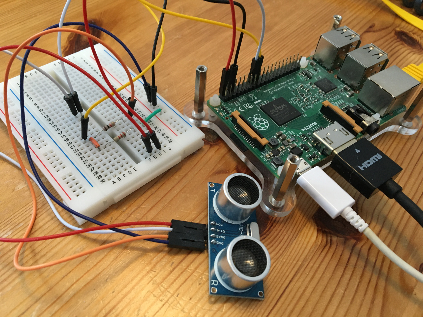
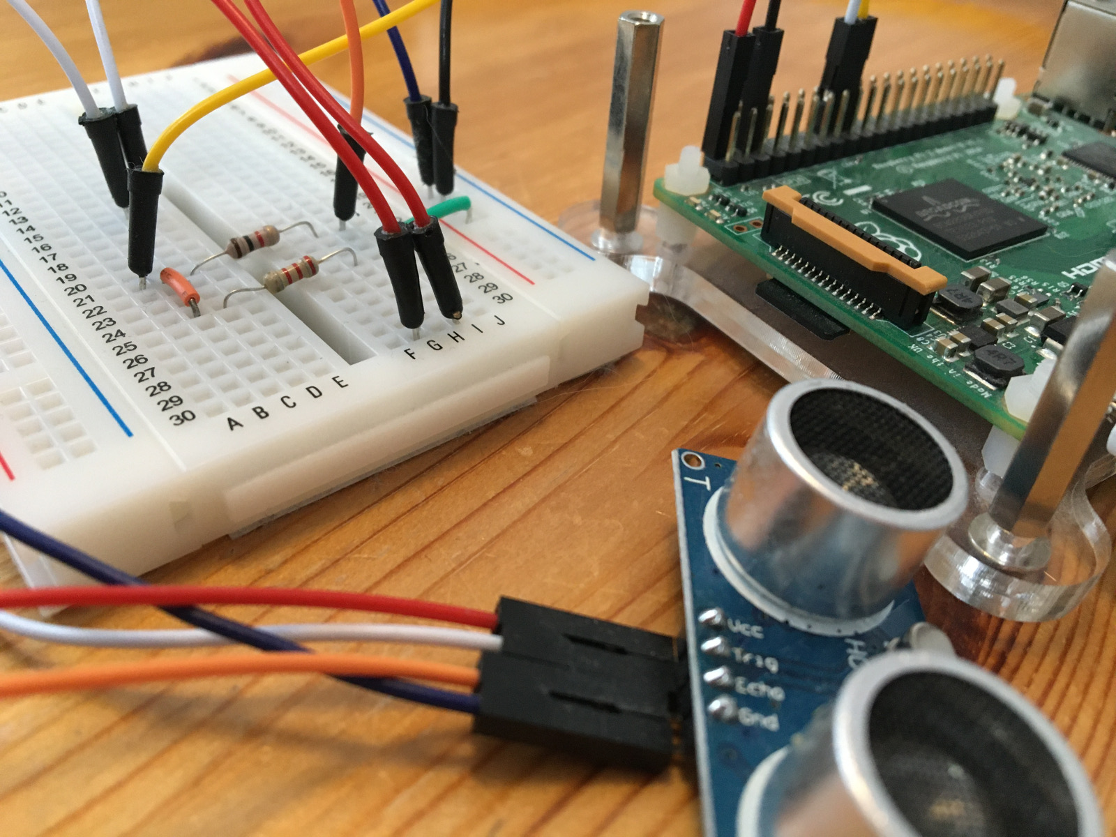
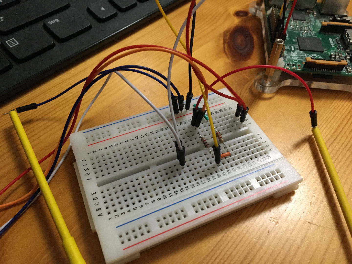
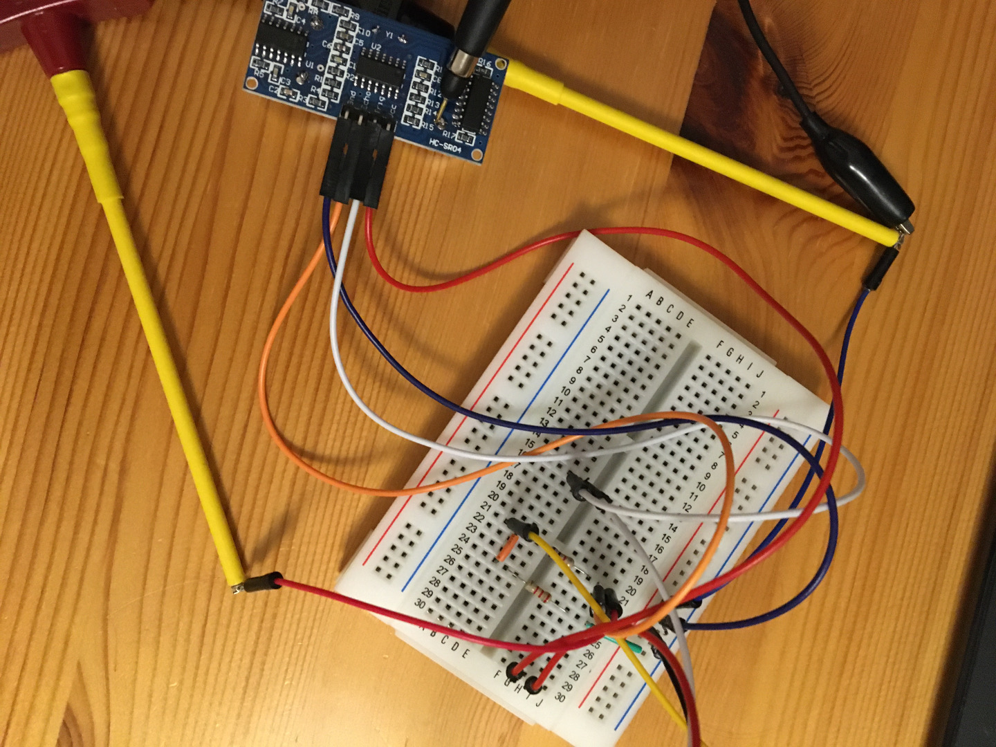
Figures 4 and 5 show my cabling, as it looks in reality (slightly messy). Figure 6 shows a screenshot of how the distance is displayed in a single line in the shell that is constantly being updated:


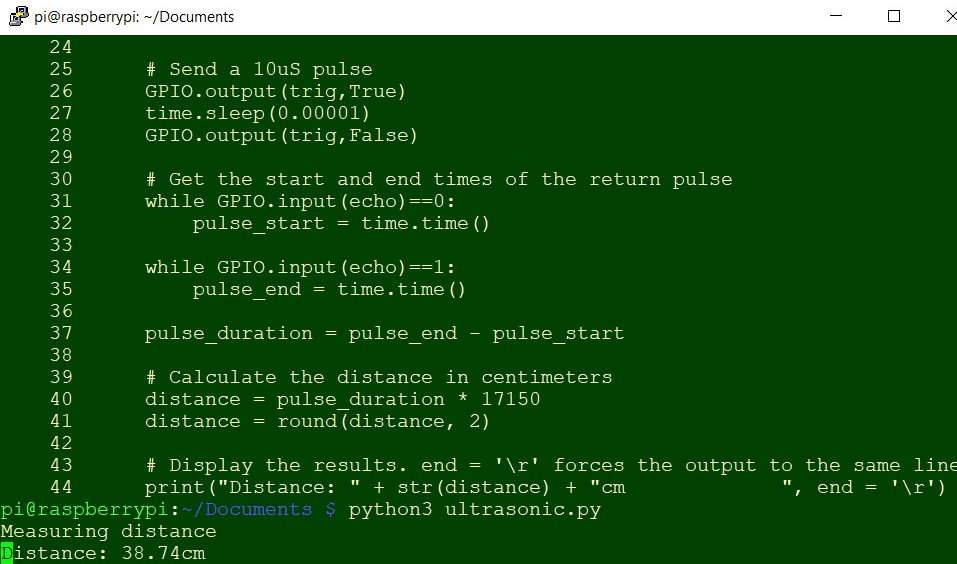
The Python code to trigger and read out the sensor can be kept quite simple. The RPi.GPIO library allows to easily configure and read-write the input/output pins on the Pi’s GPIO interface within a Python script. It is installed by default on recent versions of Raspbian Linux. The time.time() function will record the latest timestamp for a given condition. For example, if a pin goes from low to high, and we’re recording the low condition using the time.time() function, the recorded timestamp will be the latest time at which that pin was low.
1# GPIO example using an HC-SR04 ultrasonic rangefinder
2
3# import the GPIO and time libraries
4import RPi.GPIO as GPIO
5import time
6
7# Set the GPIO mode to BCM mode and disable warnings
8GPIO.setmode(GPIO.BCM)
9GPIO.setwarnings(False)
10
11# Define pins
12trig = 23
13echo = 24
14GPIO.setup(trig,GPIO.OUT)
15GPIO.setup(echo,GPIO.IN)
16print("Measuring distance")
17
18# Begin while loop
19while True:
20
21 # Set trigger pin to low for 1/10 second
22 GPIO.output(trig,False)
23 time.sleep(0.1)
24
25 # Send a 10uS pulse
26 GPIO.output(trig,True)
27 time.sleep(0.00001)
28 GPIO.output(trig,False)
29
30 # Get the start and end times of the return pulse
31 while GPIO.input(echo)==0:
32 pulse_start = time.time()
33
34 while GPIO.input(echo)==1:
35 pulse_end = time.time()
36
37 pulse_duration = pulse_end - pulse_start
38
39 # Calculate the distance in centimeters
40 distance = pulse_duration * 17150
41 distance = round(distance, 2)
42
43 # Display the results. end = '\r' forces the output to the same line
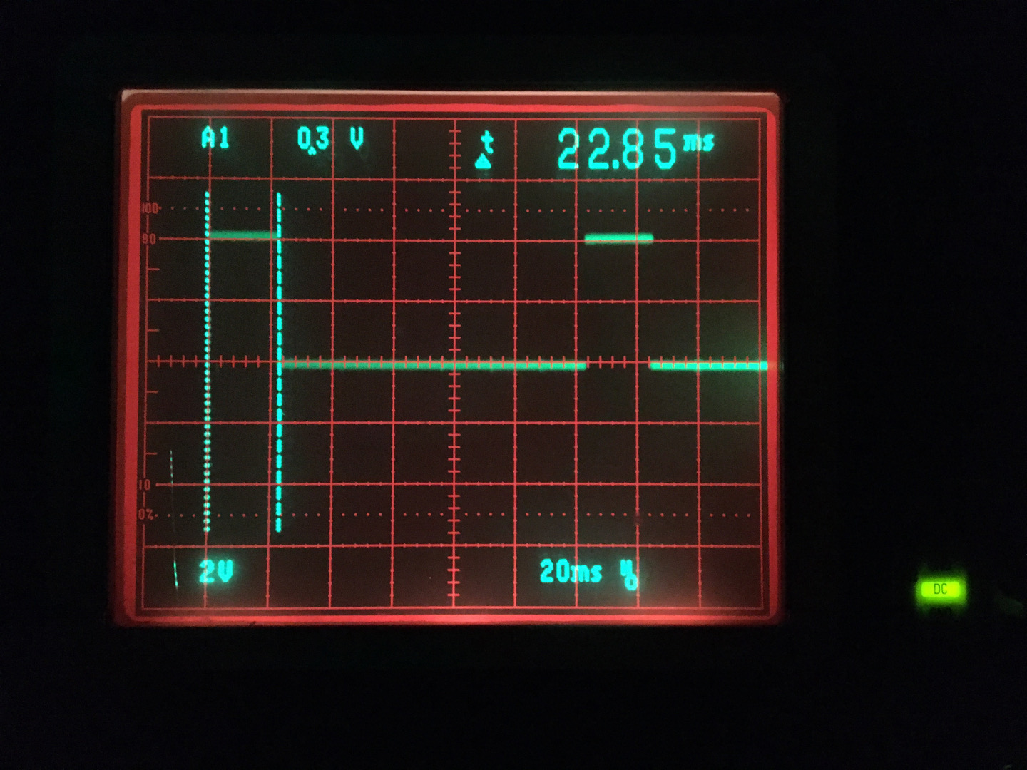
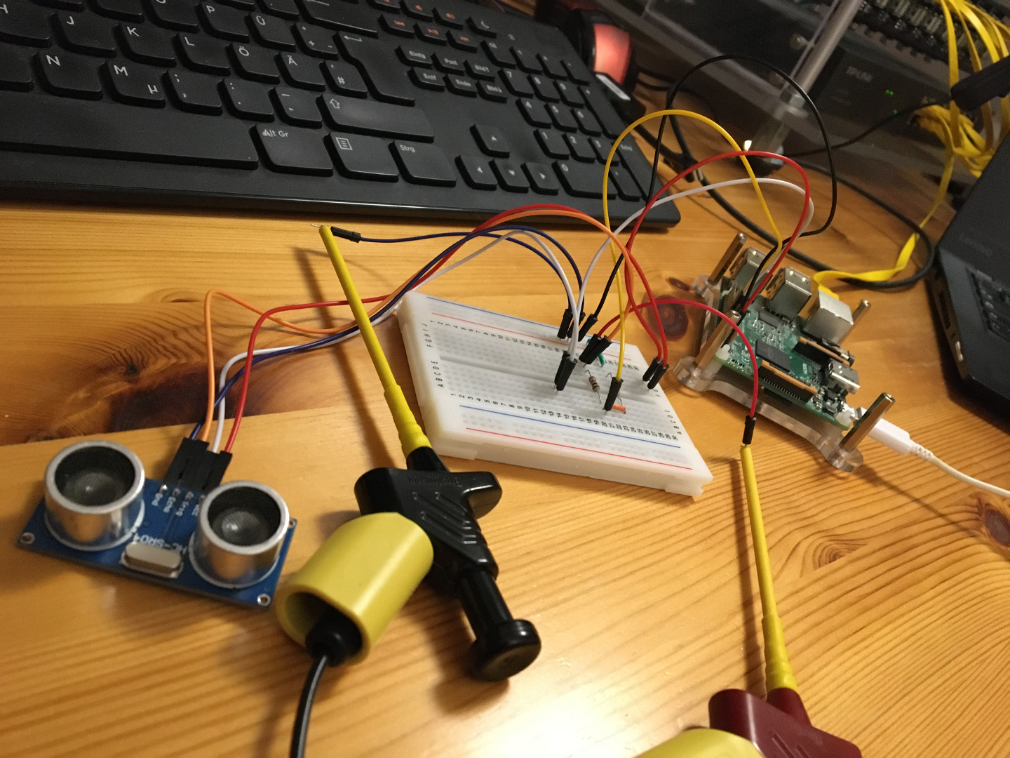
44 print("Distance: " + str(distance) + "cm ", end = '\r')Next I use my Tektronix 2465 oscilloscope to check whether the sensor really works as desribed above. Let’s first see if the distance conversion, using the speed of sound in air, works as promised. I connect the scope to GND (black) and ECHO (red/orange), as shown in Figures 7 and 8. After a short fight with the trigger, the scope shows that ECHO is high for some 23ms. Multiplying this with the speed of sound of 343m/s and dividing by 2 (round trip) yields a distance of some 3.9m which is in line with what was displayed. Nice!


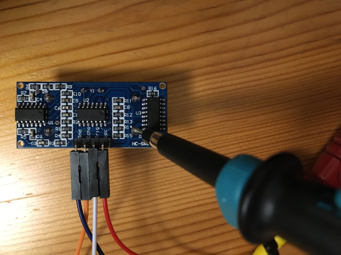
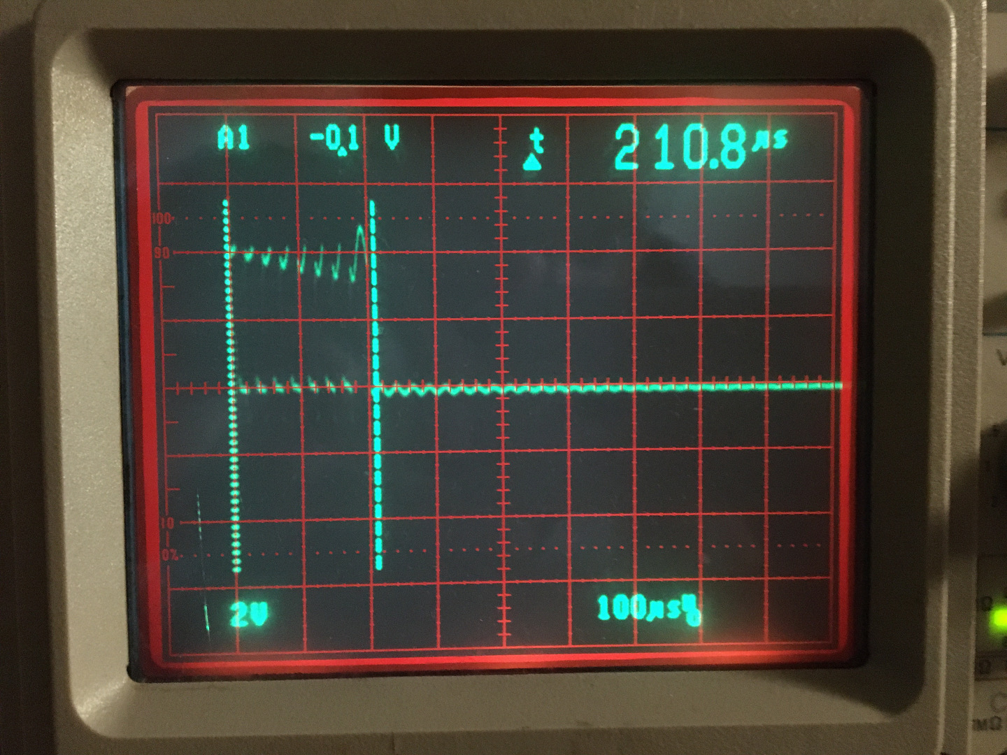
As a last step I try to take a look at the “8 burst pattern” that the sensor is supposed to send out after being triggered by the Raspberry. The letters ’T’ and ‘R’ on the front of the sensor board seem to indicate that the transmitter sits left and the receiver right. I use a probe head to connect to one of the contacts of the transmitter on the backside of the circuit board, as shown in Figures 10 and 11. The scope shows in fact 8 peaks in a time span of some 210us. The peaks thus come at a frequency of 38kHz. The description didn’t lie!
A fun GIF as a farewell from this experiment: