In my evolving robot car project it is now time to go for a test drive. More precisely, I would like to establish bidirectional communication between the Raspberry Pi, acting as spiritus rector, and the Arduino, translating abstract intention into concrete motor control with the Adafruit Motor Shield.
Basics of Serial Communication
Serial communication is the process of sending data one bit at a time, sequentially, over a communication channel or computer bus. This is in contrast to parallel communication, where several bits are sent as a whole, on a link with several parallel channels. Many communication systems were generally designed to connect two integrated circuits on the same printed circuit board, connected by signal traces on that board (rather than external cables). Integrated circuits are more expensive when they have more pins. To reduce the number of pins in a package, many ICs use a serial bus to transfer data when speed is not important. Some examples of such low-cost serial buses include RS-232, SPI, I²C, and PCI Express.
Some people specifically limit serial communication between Raspberry and Arduino to serial communication using the UART protocol, where UART stands for “Universal Asynchronous Reception and Transmission”. Basically it’s an asynchronous multi-master protocol based on the Serial communication, which will allow you to communicate between the two boards. There isn’t a common clock in asynchronous serial communication; instead, both devices keep time independently, and either send or listen for new bits of data at an agreed-upon rate.
Multi-master means that all connected devices will be free to send data when they want. This is one of the main difference with master-slaves protocols, where only the master device can initiate a communication. Usually you’ll use other protocols such as I²C and SPI when you need master-slaves configurations: for example when you have one Arduino board and multiple sensors or actuators. In contrast to UART, I²C and SPI are synchronous interfaces.
UART can also refer to a piece of computer hardware called the "Universal Asynchronous Receiver-Transmitter" (see Wikipedia). A UART is usually an individual (or part of an) integrated circuit (IC) used for serial communications over a computer or peripheral device serial port. At the origin, a UART takes bytes of data and transmits the individual bits in a sequential fashion. At the destination, a second UART re-assembles the bits into complete bytes. Each UART contains a shift register, which is the fundamental method of conversion between serial and parallel forms.
Most processors on the market today are equipped with one or more UARTs. However, most personal computers do not have an asynchronous serial port anymore. Instead, they have USB ports, which is slightly different and more complex serial protocol that allows multiple devices to communicate over the same wires (bus configuration). Because so many devices still use asynchronous serial communication, USB includes a so-called Communications Device Class (CDC) that supports asynchronous serial communication.
Devices that include a USB-to-serial converter will show up as serial ports to your computer when you plug them in. Many microcontroller boards, including the Arduino boards, include a USB-to-serial converter to communicate with your computer in this way. When you plug them in, any program that can read serial ports will list the connected Arduino in the list of serial ports.
There are two ways to connect Raspberry Pi and Arduino for serial communication:
- Serial via GPIO pins (UART, SPI, I²C)
- Serial via USB (UART)
The first way to make a serial connection is to use plain jumper wires between the Raspberry Pi GPIOs and the Arduino pins, using UART, SPI, or I²C serial protocols (see also this article). Depending on the Arduino board you might need to use a voltage level-shifter. The Raspberry Pi is operating at 3.3V. For some Arduino boards like Due this will be fine because they also use 3.3V. But for most Arduino boards, such as my Uno, the board is operating at 5V. Thus, we would need a 3.3V/5V level-shifter to protect the Raspberry Pi (as I had used for the distance sensors).
The easier way is to use a USB cable between both boards (UART protocol). I will choose this option since I anyhow need this cable, both to upload sketches from the Raspberry and to power the Arduino (but not the motor shield which has its own battery pack).
When connecting the Arduino with a USB cable, you should see it appear as /dev/ttyACM0, or /dev/ttyUSB0 (sometimes the number can be different, for example /dev/ttyACM1). Simply run ls /dev/tty* and you should see it. At this point if you’re not sure which device is the Arduino board, simply disconnect the board and run ls /dev/tty* again. This way you will easily spot the serial device name of your Arduino.
We need to initialize the serial communication both on Raspberry and Arduino and choose a baud rate. A commonly used baud rate is 9600, which is pretty low; baud rates of 57,600 or even 115,200 should also work without any problem. You need to use the same baud rate on both devices, or else everything you’ll read and write will be garbage.
Raspberry Pi Python code
On the Raspberry we need to install a library to be able to use the serial interface with Python, e.g., the commonly used pySerial library :
$ python3 -m pip install pyserialIn the Python code, serial communication is initialized by calling serial.Serial() to generate an object we can use for all serial communication:
ser = serial.Serial('/dev/ttyACM0', 9600, timeout=1)The timeout parameter is important for read operations. While we reading from serial, it will prevent us from getting stuck forever if the data is not coming. Setting timeout to x seconds (float allowed) returns immediately when the requested number of bytes are available, otherwise wait until the timeout expires and return all bytes that were received until then. The flush() function will flush any input and output buffer, so it will avoid receiving or sending weird/not useful/not complete data at the beginning of the communication.
ser.flush()In an infinite loop, similar to void loop() function in the Arduino sketch, we check if some data is available with the in_waiting attribute. The readline() function will read all bytes until a newline character is detected. You receive bytes when you read from serial, and you have to convert those bytes into the appropriate data type. So, we use decode(‘utf-8’) to decode the received data to a string. To remove any trailing characters, such as a newline \n, we apply the rstrip() function:
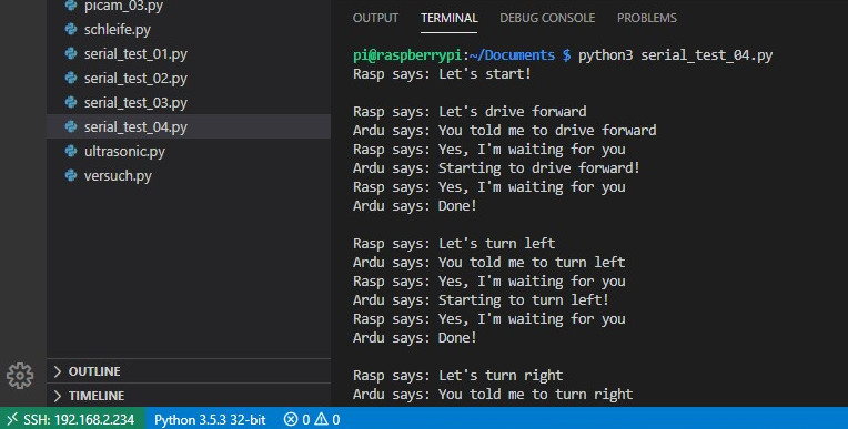
line = ser.readline().decode('utf-8').rstrip()In essence, the Python program is looping over a list called fahrprogramm that contains the actions the robot car is supposed to perform. The command strings are sent (as bytes) over the serial link to the Arduino, the end being indicated by a newline characters. The Raspberry is then entering into the infinite read loop, waiting for the Arduino to complete its action and answer "Ardu says: Done!". Then the next action is sent to the Arduino. Here is the complete listing:
#!/usr/bin/env python3

import serial
import time

fahrprogramm = [
    "drive forward\n",
    "turn left\n",
    "turn right\n",
    "turn around\n",
    "drive forward\n",
    "turn around\n"
]

time.sleep(10)

if __name__ == '__main__':
    ser = serial.Serial('/dev/ttyACM0', 9600, timeout=1)
    ser.flush()
    time.sleep(1)

    print("Rasp says: Let's start!")

    for action in fahrprogramm:
        print("\nRasp says: Let's " + action.rstrip())
        ser.write(action.encode())

        while True:
            if ser.in_waiting > 0:
                line = ser.readline().decode('utf-8').rstrip()
                print(line)
                if line == "Ardu says: Done!":
                    break
                print("Rasp says: Yes, I'm waiting for you")
                time.sleep(1)

    print("\nRasp says: OK, let's stop here!")
Arduino Code
The code on the Arduino side is also fairly straightforward.
The Adafruit_MotorShield class represents a motor shield and must be instantiated before any DCMotors or
StepperMotors can be used. You will need to declare one Adafruit_MotorShield for each shield in your system (but I currently don't see a reason why I would need more motors and shields ...). The Adafruit_MotorShield() constructor takes one optional parameter to specify the I²C address of the shield (default adress as shipped is 0x60). The function Adafruit_DCMotor *getMotor() returns one of 4 pre-defined DC motor objects controlled by the shield. A parameter 1-4 specifies the associated motor channel.
The Adafruit_DCMotor class represents a DC motor attached to the shield. You must declare one for each motor in your system. The constructor takes no arguments. The motor object is typically initialized by assigning a motor object retrieved from the shield class as below:
Adafruit_DCMotor *myMotor1 = AFMS.getMotor(1);I have defined two parameters that control the driving behavior of the robot. max_speed limits the speed to some value smaller than the actual maximum speed of 255 (the robot can drive quite fast ...). accel_delay controls how smoothly the robot accelerates and decelerates. As usual in C++ the delay is measured in milliseconds.
The Arduino setup() function is called when the sketch starts and will only run once, after each powerup or reset of the Arduino board. Here we initialize serial communication at a baud rate of 9600 and call the begin() function of the Adafruit_MotorShield class to initialize the shield. Since no PWM frequency parameter is given the default (maximum) value of 1.6KHz will be used.
In summary, the beginning of the Arduino code looks like this:
/*
This is a modification of a test sketch for the Adafruit Motor Shield
for Arduino v2 (http://www.adafruit.com/products/1438) with built-in PWM
*/

#include <Wire.h>

#include <Adafruit_MotorShield.h>

// Create the motor shield object with the default I2C address
Adafruit_MotorShield AFMS = Adafruit_MotorShield();

// Select 'ports'
Adafruit_DCMotor *myMotor1 = AFMS.getMotor(1); // front-left
Adafruit_DCMotor *myMotor2 = AFMS.getMotor(2); // back-right
Adafruit_DCMotor *myMotor3 = AFMS.getMotor(3); // front-right (reverse)
Adafruit_DCMotor *myMotor4 = AFMS.getMotor(4); // back-left (reverse)

// Variables for tweaking drive behavior
uint8_t max_speed = 120;
uint8_t accel_delay = 20;

void setup() {
  Serial.begin(9600);   // set up Serial library at 9600 bps
  Serial.println("Ardu says: Let's start!");
  AFMS.begin();         // create with the default frequency 1.6KHz
}
The Arduino loop() function loops consecutively and is used to actively control the Arduino board. It just reads commands such as "drive forward\n" from the serial port and stores them in the string state , acknowledges receipt back over the serial port, and then executes those commands by calling functions such as drive_forward(). Once a drive command is executed, state is set to `"Done!", the Arduino communicates this fact back over the serial connection to the Raspberry and waits for the next drive command.
void loop() {
  if (Serial.available() > 0) {
    String state = Serial.readStringUntil('\n');
    Serial.print("Ardu says: You told me to ");
    Serial.println(state);
    if (state == "drive forward") {
        drive_forward();
        state = "Done!";
        Serial.print("Ardu says: ");
        Serial.println(state);
        delay(1000);
    }

    [... etc ...]

    else if (state == "turn around") {
        turn_around();
        state = "Done!";
        Serial.print("Ardu says: ");
        Serial.println(state);
        delay(1000);
    } else {
      Serial.println("Ardu says: Waiting for input!");
      delay(1000);
    }
  }
}
Finally we have a set of functions that perform the actual motor control. I just show the drive_forward() function, all others look very similar.
The run() function controls the motor state. The parameter can have one the values FORWARD, BACKWARD and RELEASE. Foward and backward directions are arbitrary and can be changed by swapping the motor leads. RELEASE will simply cut power to the motor without any braking.
The setSpeed() function controls the power level delivered to the motor. The speed parameter is a value between 0 and 255. The actual speed of the motor will depend on several factors, including the motor itself, the power supply and the load. And the actual driving speed of the robot, of course, depends on many more factors, such as the gear ratio, wheel diameter, grip, mass of the robot, etc.
void drive_forward() {
  uint8_t i;
  uint16_t drive_time = 1000;

  Serial.println("Ardu says: Starting to drive forward!");

  myMotor1->run(FORWARD);
  myMotor2->run(FORWARD);
  myMotor3->run(BACKWARD);
  myMotor4->run(BACKWARD);

  for (i=0; i<max_speed; i++) {
    myMotor1->setSpeed(i);
    myMotor2->setSpeed(i);
    myMotor3->setSpeed(i);
    myMotor4->setSpeed(i);
    delay(accel_delay);
  }

  delay(drive_time);

  for (i=max_speed; i!=0; i--) {
    myMotor1->setSpeed(i);
    myMotor2->setSpeed(i);
    myMotor3->setSpeed(i);
    myMotor4->setSpeed(i);
    delay(accel_delay);
  }

}

[... etc ...]
When executing the Python code on the Raspberry and the Arduino/C++ code on the Arduino, magic happens and we see the following epic dialog in the terminal of our remote development environment in VS Code:
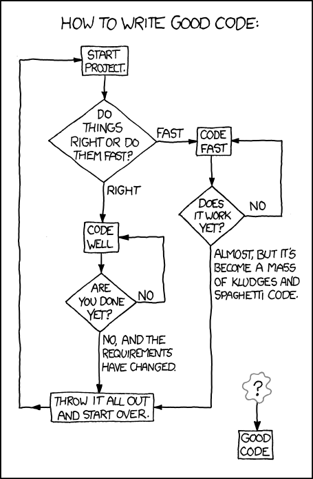
While all of this is working nicely I realize that I should learn more about the Arduino language, which subset of C/C++ functions it actually supports, and how far one can go with object oriented programming on the Arduino. Somehow the current ad-hoc implementation feels a bit like Spaghetti code:
Links
I had a hard time finding useful articles on the Internet regarding serial communication with the Raspberry which provided some conceptual understanding and went beyond displaying short code snippets. Notable exceptions are the following:
- ITP Physical Computing: Tom Igoe writing on Asynchronous Serial Communication and Synchronous Serial Communication. And then there is also this interesting lab.
- The Robotics Back-End: Raspberry Pi Arduino Serial Communication – Everything You Need To Know
- Elektronik Praxis: Raspberry Pi: Grundlagen serieller Kommunikation
- Raspberry Pi - Das technische Handbuch (Klaus Dembowski), Section 6.3 - 6.5
The Adafruit Motor Shield V2 is well documented in this PDF file. Future learning on better Arduino coding can be supported by these links:
- The Robotics Back-End: Arduino Object Oriented Programming (OOP)
- Arduino Hacking: Writing a Library for Arduino
- Arduino the Object Oriented way